Basic workflow
This section describes a basic workflow using Logic Toolkit.
Logic Behavior
To use Logic Toolkit, you need to add Logic Behavior to your GameObject.
How to create a Logic Behavior
Here, we will introduce how to create a new GameObject with Logic Behavior.
- Click the “+” button in the Hierachy window.
- Select Logic Toolkit > Logic Behavior from the menu.
- You will be in the GameObject name input mode, so press the
Enter keyto confirm.
Displaying the Logic Editor window
To edit the graph, you need to open the Logic Editor window.
Here we will show you how to open it from Logic Behavior in the Inspector window.
- In the Hierarchy window, select “Logic Behavior” that you created earlier.
- Click the “Edit” button in Logic Behavior in the Inspector window.
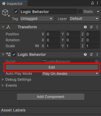
- The Logic Editor window is displayed and Logic Behavior is selected.
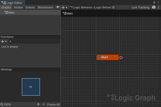
Logic Editor window UI
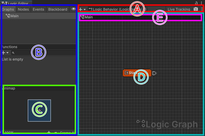
The main view we'll be using this time is (D) Graph View.
In the Graph View, you can edit the currently selected graph.
For details on the UI, see Logic Editor Window.
Edit graph
Let's edit the main graph of the currently selected Logic Behavior.
Creating a Task node
Let's place task nodes that perform processing on the graph.
Here, we will create Wait For Seconds that waits for a specified number of seconds.
- Left-click on the graph view to focus it.
- Press the
Spacebaron your keyboard (default shortcut setting). - Select Tasks > Wait For Seconds from the node menu.
- The node will be created and you will be able to edit the node name. Press the
Enter keyto complete the rename.
*Here, we will leave the node name as the default for the sake of explanation, but we recommend setting it appropriately when performing full-scale development.
Node UI
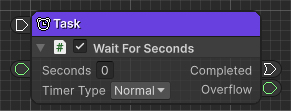
We will explain the node UI using the created “Task” node as an example.
Header section
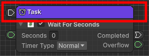
The node name and major input/output ports are displayed.
Node component
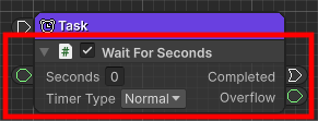
Node processing is controlled by scripts called node components.
This time, a component script called Wait For Seconds is assigned.
Editing a node component
Wait For Seconds has several fields and ports.
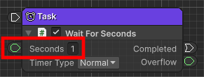
This time, let's set the Seconds field to 1.
- Click the input field of the Seconds field in Wait For Seconds of the Task node.
- Enter
1.
Connecting nodes
Connect nodes by dragging the ports displayed around the nodes.
When you drag a port, ports that can be connected are highlighted in yellow, so drop it where you want to connect.
- Drag the output port on the right side of the Start node that is placed from the beginning
- Drop it onto the input port on the left side of the Task node you created earlier.
ExecuteWire

The output port on the right side of the Start node and the Task node were connected by ExecuteWire.
This ExecuteWire means the wire (wire connecting ports) for executing the connected node.
In this case, the Start node will first execute the Task node, which is the node to which it is connected with ExecuteWire.
See ExecuteWire for details.
Creating an Action node
Let's execute an action after waiting is completed with Wait For Seconds.
Here we will use an action component script called Debug.Log which outputs debugging output.
- Drag the output port to the right of the Completed field of Wait For Seconds
- Move the mouse cursor to the right from there and drop it somewhere on the graph
- Select Actions > Debug > Debug.Log from the node menu that appears
- The node will be created and you will be able to edit the node name. Press the
Enter keyto complete the rename.
In this way, if you drag a port and drop it on an empty spot on the graph, a menu of nodes that can be connected to the port being dragged will be displayed, and the port will be connected when the node is created.
TransitionWire

The Task node and Action node were connected by TransitionWire.
TransitionWire means a wire (a line connecting ports) for transitioning execution nodes.
In this case, when the Task node's Wait For Seconds is completed, it will transition to the Action node, which is the node to which the Completed port is connected.
See TransitionWire for details.
About the executor
There are two types of wires that have appeared so far, but the one that performs the node execution process is the connection of ExecuteWire. It is being done.
If the node (executor) on the output port side of ExecuteWire becomes inactive, the execution of the connected node will also be disabled. Stop.
Setting Debug.Log
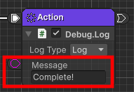
Let's temporarily display the message “Complete!".
- Click the input field of the Message field in Debug.Log of the Action node.
- Type
Complete!
Play to see if it works
Once you have configured this, let's play and see how it works.
- Messages in Debug.Log are displayed in the Console window.
If it is not open, select “Window > General > Console” from the menu. - Click the play button at the top of Unity
In the video, the Playmode tint has been changed to red to make the playmode easier to understand.
Take a look at the Logic Editor window while you play.
The active nodes are highlighted with a blue frame, so you can visually check which nodes are in operation.
When the Action node's Debug.Log is executed, “Complete!” will be displayed in the Console window.
After that, the only active node is the Start node, and nothing changes after that.
Repeat
Now, let's wait 1 second and repeat the “Complete!” display.
It is also possible to connect the Action node's output port to the Task node's input port,
but Here, we will use the convenient flow termination node Restart.
- Drag the output port of the Action node
- Move the mouse cursor to the right from there and drop it somewhere on the graph
- Select Flow Controls > Restart from the node menu
Flow exit node
This Restart is called a flow termination node, and it is a node that notifies the executing port of the end of execution.
It is passed back to the executing node, and termination processing is performed by various nodes.
This time, Restart will be notified to the Start node.
If the Start node is notified of Restart, it will restart execution from the first node.

Play again
Let's play again and see how it works.
- Messages in Debug.Log are displayed in the Console window.
If it is not open, select “Window > General > Console” from the menu. - Click the play button at the top of Unity
In the video, the Playmode tint has been changed to red to make the playmode easier to understand.
“Complete!” is now displayed repeatedly at 1 second intervals.
This is the basic workflow.