Overview
Logic Toolkit is an editor extension asset of the Visual Scripting category that allows you to construct the flow of behavior in a visual node graph format.
Visualize the flow of behavior
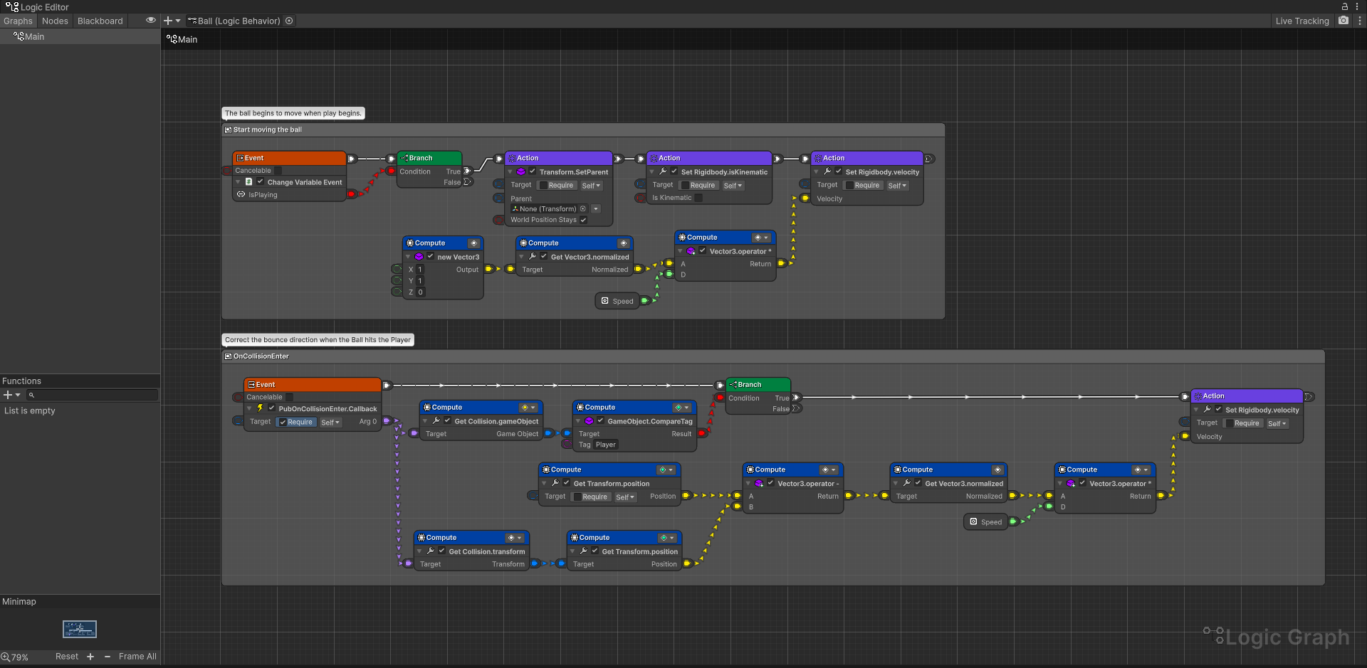
The Unity Editor extension window allows you to visually edit your node graph.
Test play on Unity allows you to check the current values of running nodes and data, which is also useful for debugging.
3 concepts
Logic Toolkit achieves high reusability by structuring the flow of behavior into three general concepts.
Action
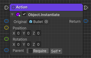
For example, a process that can be completed in an instant, such as firing a bullet (materializing a bullet object), is called an action here. (Also called synchronous processing in programming terminology)
Processing such as storing or retrieving the number of remaining bullets in a variable, or determining whether there are any remaining bullets, can also be considered a type of action.

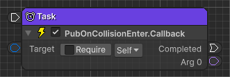
Task
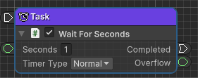
For example, processes that are performed continuously, such as “wait for a certain period of time” or “move in a straight line from point A to point B and wait until the movement is complete” are called tasks here. (Also called asynchronous processing in programming terminology)
Event
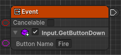
For example, the process of waiting for “when a key is input” or “when an object collides with something” is called an event here. (Also called an event in programming terminology)
You can also think of “tasks that wait until an event arrives”, so you can also use the event function where you can use the task function.
4 flows
Logic Toolkit organizes the processing flow into four categories.
Execution flow
The flow of what kind of processing is to be done and in what order is called the execution flow here.
For example, if a character is attacked, the flow will be as follows.
- Damage calculation
- Show hit effect
- Has your physical strength become 0 or less?
- Death animation play
- Wait for a certain amount of time to pass
- Destroy object

State machine
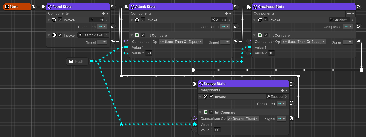
A process flow that focuses on “states” and “conditions for switching states” is called a state machine.
For example, there are enemy monsters that have built state machines like the one below.
| State | Description | Transition |
|---|---|---|
| Patrol | Patrol a fixed route in search of player characters | Go to “Normal attack” state when a player is found |
| Normal attack | Approaches the player and attacks normally | Goes into “Goes crazy” state when less than half of his health remains |
| Goes crazy | Attack power increases by 1.5 times and attacks aggressively | Goes into “Escape” state when remaining health is 10% or less |
| Escape | Move away from the player and wait for your own physical strength to recover naturally | If your physical strength has recovered to more than half, go to the “Normal attack” state. |
Behavior tree
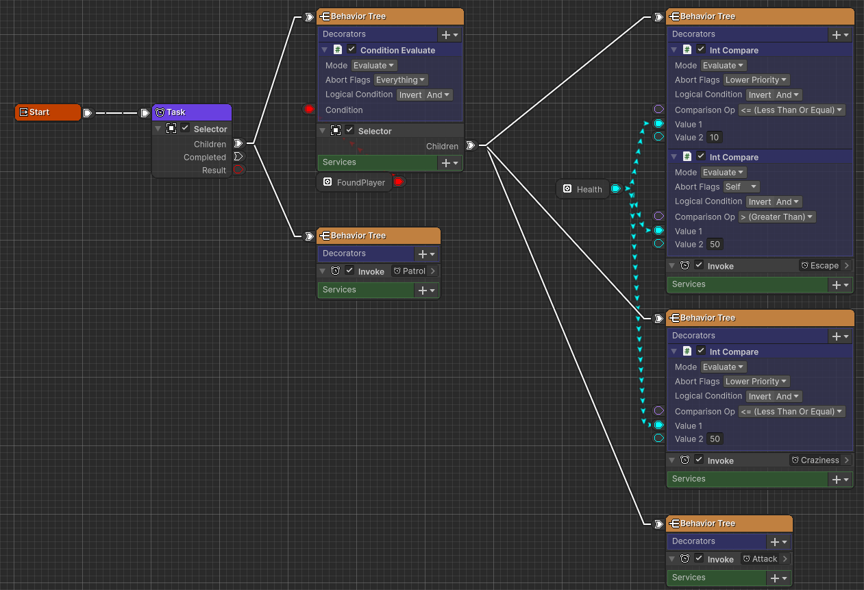
The flow of processing that focuses on “priorities” and “conditions for behavior” is called a behavior tree.
For example, the behavior of an enemy monster can be expressed in a behavior tree as shown below.
| Priority | Behavior | Condition | Description |
|---|---|---|---|
| 1 | Ready for battle | Found a player | Ready for battle by taking the following actions against the player you found |
| 1-1 | Escape | Less than 10% of your health remaining | Move away from the player and wait for your health to recover naturally |
| 1-2 | Going crazy | Less than half of your health left | Performs a powerful attack |
| 1-3 | Normal attack | Unconditional | Approach the player and attack normally |
| 2 | Patrol | Unconditional | Search for player characters and patrol a fixed route |
(Due to the tree structure, child elements are represented here as “1-1”)
Data flow
The flow of data that performs values acquisition, calculations, etc. is called data flow here.
For example, the damage calculation is as follows.
- Get attack power
- Get defensive power
- Get remaining health
- Calculate “Remaining Health - (Attack Power/2 - Defense Power/4)”
- Set the remaining health to the value in 4.

Nodes
Logic Toolkit allows you to realize the above “4 concepts” and “4 flows” with various nodes.
Action

A node that performs a single process.
It runs instantly and immediately transitions to the next node.
For details, see Action.
Task

A node that continuously executes processing.
Wait until the process is completed and then transition to the next node.
For details, see Task.
Flow control nodes
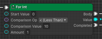
A group of nodes that control the execution flow of nodes.
You can branch the node to be executed and repeatedly execute the connected node.
For details, please refer to Flow control nodes.
Event nodes

A group of nodes for starting node execution. According to the execution start conditions, if the conditions are met, execute the connected node.
For details, please refer to Event nodes.
State
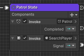
This is a node that handles states.
The execution status is sent as a signal, and the connected signal node transitions to the next node depending on the result of the condition judgment.
For details, see State.
Signal nodes
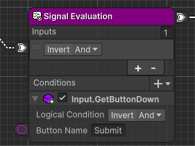
A group of nodes that determine conditions for transitioning from State to other nodes.
For details, please refer to Signal nodes.
BehaviorTree
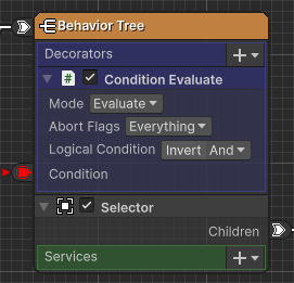
This node switches execution nodes in behavior tree format.
They are executed in the priority order of the connected nodes, and the child nodes return their execution results to the parent node, and the parent node controls the execution of the child nodes based on the received results.
For details, see BehaviorTree.
Data calculation nodes
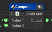
A group of nodes for performing arithmetic operations, obtaining values, etc.
For details, please refer to Data calculation nodes.
Data conversion nodes

A group of nodes for converting data types.
For details, please refer to Data conversion nodes.
Node Component

A node component is a component for a node that implements the behavior. By setting a node component to a node, you can configure how the running node behaves.
For details, see Node Component.
C# scripts
Various node components can be added using C# scripts.
Processes that would be too complex on a graph can be easily organized by writing C# scripts.
For details, see Scripting.
Float Sub script code example
|
|
Generate API call script
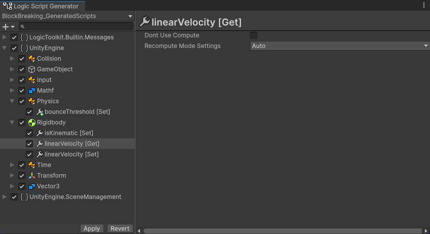
You can generate scripts for node components to call APIs such as Unity itself and packages.
The necessary node components are generated just by selecting the member you want to call, so you can concentrate on editing the node graph without having to write simple scripts.
For details, see Script generation.